
ACTUATORS - AC MOTORS
AC Motor AC Motor
note: I have never actually used an AC motor, so feel free to correct and verify this information
note: this page is a place holder until a better tutorial is written
Unlike DC motors which work using a single constant current, AC motors run under 3 phase current. To have 3 phase power on a robot, you either need a big bulky/expensive DC->AC converter, or you must tether it to a wall socket. You probably won't use AC motors unless your robot is stationary, such as a robot arm or robot pancake maker. Unless you want the pancake maker to also walk your dog or something . . . But here they are anyway:
Voltage
* Polarized (current cannot be reversed)
* Typically from 120-240V AC, usually to match mains power
* Higher voltages generally mean more torque, but also require more power
* Rarely used on mobile robots due to power requirements
* note: A universal motor has brushes like a DC motor, but will operate on AC or DC
Current
* When buying a motor, consider stall and operating current (max and minimum)
* Stall Current - The current a motor requires when powered but held so that it does not rotate
* Operating Current - The current draw when a motor experiences zero resistance torque
* It is best to determine current curves relating voltage, current, and required torque for optimization
* When a motor experiences a change in torque (such as motor reversal) expect short lived current spikes
* Current spikes can be up to 2x the stall current, and can fry control circuitry if unprotected
* Use diodes to prevent reverse current to your circuitry
* Check power ratings of your circuitry and use heat sinks if needed
Power (Root-Mean Squared Voltage x Current)
* Running motors close to stall current often, or reversing current often under high torque, can cause motors to melt
* Heat sink motors if not avoidable
Torque
* When buying a motor, consider stall and operating torque (max and minimum)
* Stall Torque - The torque a motor requires when powered but held so that it does not rotate
* Operating Torque - The torque a motor can apply when experiencing zero resistance torque
Velocity
* Motors run most efficient at the highest possible speeds
* Gearing a motor allows the motor to run fast, yet have a slower output speed with much higher torque
* Remember that torque determines acceleration, so a fast robot with poor acceleration is really a slow robot
* If uncertain, favor torque over velocity
Efficiency
* More efficient than DC motors
* Typically most efficient at rated voltage and frequency
* Use gearing (opt to buy motors with built-in gearing or gear heads)
Control Methods
* Modifying the AC frequency can alter speed and torque
* Encoder - device which counts rotations of wheel or motorshaft to determine velocity for a control feedback loop
* Tachometer - device which measures current draw of motor to control output torque
This circuit will allow you to control the speed of an AC motor.
The bridge rectifier produces DC voltage from the 120VAC line.
A portion on this current passes through the 10K ohm pot.
The circuit comprised of the 10k pot rated at 3W+, the two 100 ohm resistors and the 50uf capacitors delivers gate drive of the SCR.
The diode D1 protects the circuit from reverse voltage spikes.
The ratings of the bridge rectifier and the SCR should be 25 amps and PIV 600 volts.
The diode D1 should be rated for 2 amps with PIV of 600 volts.
The circuit can handle a load up to 10 amps. The SCR should be very well heat sinked.
AC Motor Speed Control Schematic
Saturday, December 29, 2007
ACTUATORS


Saturday, December 15, 2007
BEGINNER TO ROBOTICS


Hi Guys,
I hope the funda of C.G location, drives, gears,etc is clear from the past two chapters.
Now lets begin with the 3rd chapter ie. The circuitry of a normal robotic car.
This circuitry will enable the robo to move forward, backward, left and right.
Now starting with circuitry we need 2 two way switches. These switches conduct in both directions hence the name two way switches.
Firstly we sort the terminals
- 1 and 6 { first switch}
- 2 and 5 { “ }
- 1’ and 6’ { second switch}
- 2’ and 5’ { “ }
Then we choose the terminals of first switch ie. 5 as positive or 6 as positive . either way one wants to, can do so.
But one thing has to be kept in mind that if 5 is positive in 1st switch then 5’ should be the + ve terminal of 2nd switch.
The same convention for negative terminal.
POWER SUPPLY - Terminals 3,4 from 1st switch and terminals 3’, 4’ from 2nd switch are the power supply terminals.
In this too we have to use the same convention like the +ve and –ve terminals of either switches.
If we take 3 as +ve than we have to take 3’ as +ve and give this combined combination to the powe supply as +ve.
The same case for negative ie. Combination of 4 and 4’ for negative.
Or the reverse can also be done. - The terminals 3 and3’ are sorted with the help of wires and similarly we sort the terminals 4 and 4’.
The output single wire from 3 and 3’ combination will be given to + ve of the power supply and the output single wire from the combination of 4 and 4’ will be given to the – ve of the power supply. - Power supply can be an adaptor or an eliminator of 12 volts.
This is the connection we make in switch. Now how to proceed with combining this connection with motors.
MOTOR CONNECTION
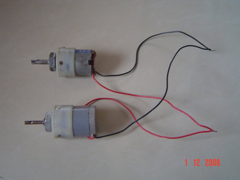
We will call the top and bottom motors on left hand side the left pair and
The top an bottom motors on right side the right pair
The above picture shows the left pair . similarly we have to connect the right pair.
LEFT PAIR MOTORS
We will bring together the positive of both the top and bottom motor on left hand side and sort them . similarly we will sort the negative of both the motors of the left pair.
RIGHT PAIR MOTORS
Now as we did in the left pair we will sort the +ve wire of both motors together and sort the –ve of the motors .
So in all we get 4 output wires from the motor connection .
2 from left pair and 2 from right pair.
COMBINING THE SWITCH AND MOTOR CIRCUIT
Now to connect the switch to motors we have to choose four output from the switch connection as we have four output from the motor connection.
We will consider the terminal 5 and 6 from the first switch and 5’ and 6’ from second switch.
Considering the terminal 5 from first switch positive terminal 5’ will be positive from second switch. Similarly 6 and 6’ are considered as negative.
Now the connection goes this way
positive wire combination from left pair motors will be connected to point 5
negative wire combination from left pair motors will be connected to point 6
positive wire combination from right pair will be connected to point 5’
negative wire combination from right pair will be connected to point 6’
these connections are made with the help of intermediate wires called the rainbow wires. I suppose…..
these are a bunch of thin wires used for internal circuitry.
If suppose u connect positive wire from left hand pair from motors to red wire then the other end of red wire will be connected to point 5.
Similarly for all connections.
The length of the intermediate wire depends on the user. Normally we take 8 to 9 meters. That will be the range of your robo.
Subscribe to:
Posts (Atom)


