

Hi Guys,
I hope the funda of C.G location, drives, gears,etc is clear from the past two chapters.
Now lets begin with the 3rd chapter ie. The circuitry of a normal robotic car.
This circuitry will enable the robo to move forward, backward, left and right.
Now starting with circuitry we need 2 two way switches. These switches conduct in both directions hence the name two way switches.
Firstly we sort the terminals
- 1 and 6 { first switch}
- 2 and 5 { “ }
- 1’ and 6’ { second switch}
- 2’ and 5’ { “ }
Then we choose the terminals of first switch ie. 5 as positive or 6 as positive . either way one wants to, can do so.
But one thing has to be kept in mind that if 5 is positive in 1st switch then 5’ should be the + ve terminal of 2nd switch.
The same convention for negative terminal.
POWER SUPPLY - Terminals 3,4 from 1st switch and terminals 3’, 4’ from 2nd switch are the power supply terminals.
In this too we have to use the same convention like the +ve and –ve terminals of either switches.
If we take 3 as +ve than we have to take 3’ as +ve and give this combined combination to the powe supply as +ve.
The same case for negative ie. Combination of 4 and 4’ for negative.
Or the reverse can also be done. - The terminals 3 and3’ are sorted with the help of wires and similarly we sort the terminals 4 and 4’.
The output single wire from 3 and 3’ combination will be given to + ve of the power supply and the output single wire from the combination of 4 and 4’ will be given to the – ve of the power supply. - Power supply can be an adaptor or an eliminator of 12 volts.
This is the connection we make in switch. Now how to proceed with combining this connection with motors.
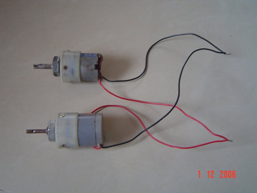
MOTOR CONNECTION
We will call the top and bottom motors on left hand side the left pair and
The top an bottom motors on right side the right pair
The above picture shows the left pair . similarly we have to connect the right pair.
LEFT PAIR MOTORS
We will bring together the positive of both the top and bottom motor on left hand side and sort them . similarly we will sort the negative of both the motors of the left pair.
RIGHT PAIR MOTORS
Now as we did in the left pair we will sort the +ve wire of both motors together and sort the –ve of the motors .
So in all we get 4 output wires from the motor connection .
2 from left pair and 2 from right pair.
COMBINING THE SWITCH AND MOTOR CIRCUIT
Now to connect the switch to motors we have to choose four output from the switch connection as we have four output from the motor connection.
We will consider the terminal 5 and 6 from the first switch and 5’ and 6’ from second switch.
Considering the terminal 5 from first switch positive terminal 5’ will be positive from second switch. Similarly 6 and 6’ are considered as negative.
Now the connection goes this way
positive wire combination from left pair motors will be connected to point 5
negative wire combination from left pair motors will be connected to point 6
positive wire combination from right pair will be connected to point 5’
negative wire combination from right pair will be connected to point 6’
these connections are made with the help of intermediate wires called the rainbow wires. I suppose…..
these are a bunch of thin wires used for internal circuitry.
If suppose u connect positive wire from left hand pair from motors to red wire then the other end of red wire will be connected to point 5.
Similarly for all connections.
The length of the intermediate wire depends on the user. Normally we take 8 to 9 meters. That will be the range of your robo.


1 comment:
This is cool stuff. I hope to spend more time reading through your blog. It appears you have a good thorough collection of articles!
I'm just getting back into robotics after a several years hiatus. I have been interested in the field since around 1992. Feel free to send me an email if you like.
Cheers,
Michael
Post a Comment