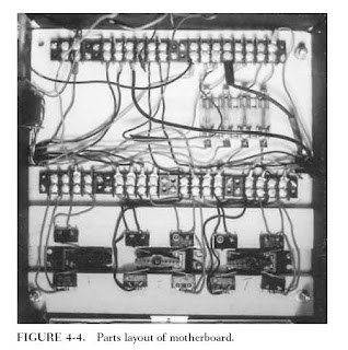
The motherboard is simply a 10-10-1/8-inch piece of plywood on which all of the components for the remote control system are mounted. The various components consist of the remote control system’s servos, receiver, and battery pack, along with ten leaf switches, four barrier strips, and a four-slot fuse holder. Figure 4-4 shows where each item is placed on the board.
The first items to be mounted are the servos. Cutouts will have to be made in the board to allow the servos to sit flush with the board. To do this, first place the servos evenly spaced on the motherboard and trace around their bases. Cut out the wood where traced and slip the servos in place. The servos’ body should have tabs sticking out along its top edge; these tabs prevent the servo from going all the way
through the board and this is where the servos are screwed to the board. Most remote control systems come with either plastic wheels and/or star levers that are screwed on the servo’s motor.
WIRING THE MOTHERBOARD:
Before you wire the motherboard, cut two notches on each side of the motherboard so the wires will not go past its edge. Figure 4-8 shows how to wire together the components on the motherboard. There are two main rows of barrier strips on the
motherboard; the first row is numbered.
These numbers correspond with numbers on the tabs of the leaf switches; simply wire the matching numbers together. In some cases more than one wire will go to one post on the barrier strip. Use the half of the barrier strip closest to the leaf switches. The color wire used is indicated on the leaf switch: R _ red, B _ black. The other row is where the motorized wheel and horn will be connected; they too use the matching number system.
The second row is divided into two parts called power grids. The first 8 post (which is one complete barrier strip) is called the positive grid and is where the positive lead of the battery is connected and where all the positive or red wires from Questor’s electronics will be connected. The second 8 post is for the negative or black wires and is called the negative power grid. All the posts on the same side of each grid must be wired together by one wire run from post to post.
Be sure not to run a wire between the positive and negative grids; this will cause a short circuit. Figure 4-8 shows where the wire runs. Later when other functions are wired, the instructions will say “wire to positive power grid and negative power grid.” You can then connect those wires to any open post on the grids. Figure 4-8 also shows four wires coming from the positive grid to the fuse holder. These wires are all positive and you should use red wires.
Two more red wires run from the opposite ends of two of the fuses directly to the post on the leaf switch barrier strips. This is where the switch gets the power to control two on/off functions in the robot. (The negative or black wire forms the function being controlled; in my robot a horn is wired directly to the positive power grid.) There are also two black wires running from the negative power grid to the leaf switch barrier strips at post 8 and 2.
These are also shown in figure below...
Wires to the leaf switches and fuse holder will have to be soldered. The wires that lead to the barrier strips should have hooks bent at their ends so they can wrap around the screws on the strip. After the board is wired, check it against Figure because errors here can affect the function of the rest of the robot. Also at this time, install four 20-amp fuses
in the fuse holder. These fuses help protect the robot’s components from short circuits and overloads. Once the board is wired and checked, the remote control receiver can
be mounted and the motherboard mounted in Questor’s framework.
COMPLETING THE MOTHERBOARD:
The remote control’s receiver and battery are mounted on the underside of the motherboard. Using four screw-on hooks, rubber bands and foam rubber, the receiver is held securely in place. Figure shows how to mount the receiver. The figure
is self-explanatory. The only thing to keep in mind is that the servos must be wired to the receiver, so don’t mount the receiver out of reach of the servo wires.
The order in which the servos are connected to the receiver is very important to the control of the robot. When both control sticks on the transmitter are pushed up, the
robot should move forward. If both sticks are pulled down, the robot should run in reverse. The center or neutral position is off and of course causes no movement of the robot. If you have a third channel (and servo) in your remote control system, it should react to the sideways movement of one of the control sticks on the transmitter.
Table 4-2 lists all of the control combinations used to operate Questor’s functions. It is not necessary to wire the motorized wheels to the motherboard. To check this simply make sure that when thesticks are pushed forward, the two servos controlling the motorized wheels turn as shown in Fig. 4-10. If you have a third servo a sideways movement of either stick should causethe servo to activate it.
Tuesday, April 1, 2008
MOTHERBOARD
Subscribe to:
Post Comments (Atom)


No comments:
Post a Comment