ACTUATORS - AC MOTORS
AC Motor AC Motor
note: I have never actually used an AC motor, so feel free to correct and verify this information
note: this page is a place holder until a better tutorial is written
Unlike DC motors which work using a single constant current, AC motors run under 3 phase current. To have 3 phase power on a robot, you either need a big bulky/expensive DC->AC converter, or you must tether it to a wall socket. You probably won't use AC motors unless your robot is stationary, such as a robot arm or robot pancake maker. Unless you want the pancake maker to also walk your dog or something . . . But here they are anyway:
Voltage
* Polarized (current cannot be reversed)
* Typically from 120-240V AC, usually to match mains power
* Higher voltages generally mean more torque, but also require more power
* Rarely used on mobile robots due to power requirements
* note: A universal motor has brushes like a DC motor, but will operate on AC or DC
Current
* When buying a motor, consider stall and operating current (max and minimum)
* Stall Current - The current a motor requires when powered but held so that it does not rotate
* Operating Current - The current draw when a motor experiences zero resistance torque
* It is best to determine current curves relating voltage, current, and required torque for optimization
* When a motor experiences a change in torque (such as motor reversal) expect short lived current spikes
* Current spikes can be up to 2x the stall current, and can fry control circuitry if unprotected
* Use diodes to prevent reverse current to your circuitry
* Check power ratings of your circuitry and use heat sinks if needed
Power (Root-Mean Squared Voltage x Current)
* Running motors close to stall current often, or reversing current often under high torque, can cause motors to melt
* Heat sink motors if not avoidable
Torque
* When buying a motor, consider stall and operating torque (max and minimum)
* Stall Torque - The torque a motor requires when powered but held so that it does not rotate
* Operating Torque - The torque a motor can apply when experiencing zero resistance torque
Velocity
* Motors run most efficient at the highest possible speeds
* Gearing a motor allows the motor to run fast, yet have a slower output speed with much higher torque
* Remember that torque determines acceleration, so a fast robot with poor acceleration is really a slow robot
* If uncertain, favor torque over velocity
Efficiency
* More efficient than DC motors
* Typically most efficient at rated voltage and frequency
* Use gearing (opt to buy motors with built-in gearing or gear heads)
Control Methods
* Modifying the AC frequency can alter speed and torque
* Encoder - device which counts rotations of wheel or motorshaft to determine velocity for a control feedback loop
* Tachometer - device which measures current draw of motor to control output torque
This circuit will allow you to control the speed of an AC motor.
The bridge rectifier produces DC voltage from the 120VAC line.
A portion on this current passes through the 10K ohm pot.
The circuit comprised of the 10k pot rated at 3W+, the two 100 ohm resistors and the 50uf capacitors delivers gate drive of the SCR.
The diode D1 protects the circuit from reverse voltage spikes.
The ratings of the bridge rectifier and the SCR should be 25 amps and PIV 600 volts.
The diode D1 should be rated for 2 amps with PIV of 600 volts.
The circuit can handle a load up to 10 amps. The SCR should be very well heat sinked.
AC Motor Speed Control Schematic
Saturday, December 29, 2007
ACTUATORS
Saturday, December 15, 2007
BEGINNER TO ROBOTICS


Hi Guys,
I hope the funda of C.G location, drives, gears,etc is clear from the past two chapters.
Now lets begin with the 3rd chapter ie. The circuitry of a normal robotic car.
This circuitry will enable the robo to move forward, backward, left and right.
Now starting with circuitry we need 2 two way switches. These switches conduct in both directions hence the name two way switches.
Firstly we sort the terminals
- 1 and 6 { first switch}
- 2 and 5 { “ }
- 1’ and 6’ { second switch}
- 2’ and 5’ { “ }
Then we choose the terminals of first switch ie. 5 as positive or 6 as positive . either way one wants to, can do so.
But one thing has to be kept in mind that if 5 is positive in 1st switch then 5’ should be the + ve terminal of 2nd switch.
The same convention for negative terminal.
POWER SUPPLY - Terminals 3,4 from 1st switch and terminals 3’, 4’ from 2nd switch are the power supply terminals.
In this too we have to use the same convention like the +ve and –ve terminals of either switches.
If we take 3 as +ve than we have to take 3’ as +ve and give this combined combination to the powe supply as +ve.
The same case for negative ie. Combination of 4 and 4’ for negative.
Or the reverse can also be done. - The terminals 3 and3’ are sorted with the help of wires and similarly we sort the terminals 4 and 4’.
The output single wire from 3 and 3’ combination will be given to + ve of the power supply and the output single wire from the combination of 4 and 4’ will be given to the – ve of the power supply. - Power supply can be an adaptor or an eliminator of 12 volts.
This is the connection we make in switch. Now how to proceed with combining this connection with motors.
MOTOR CONNECTION
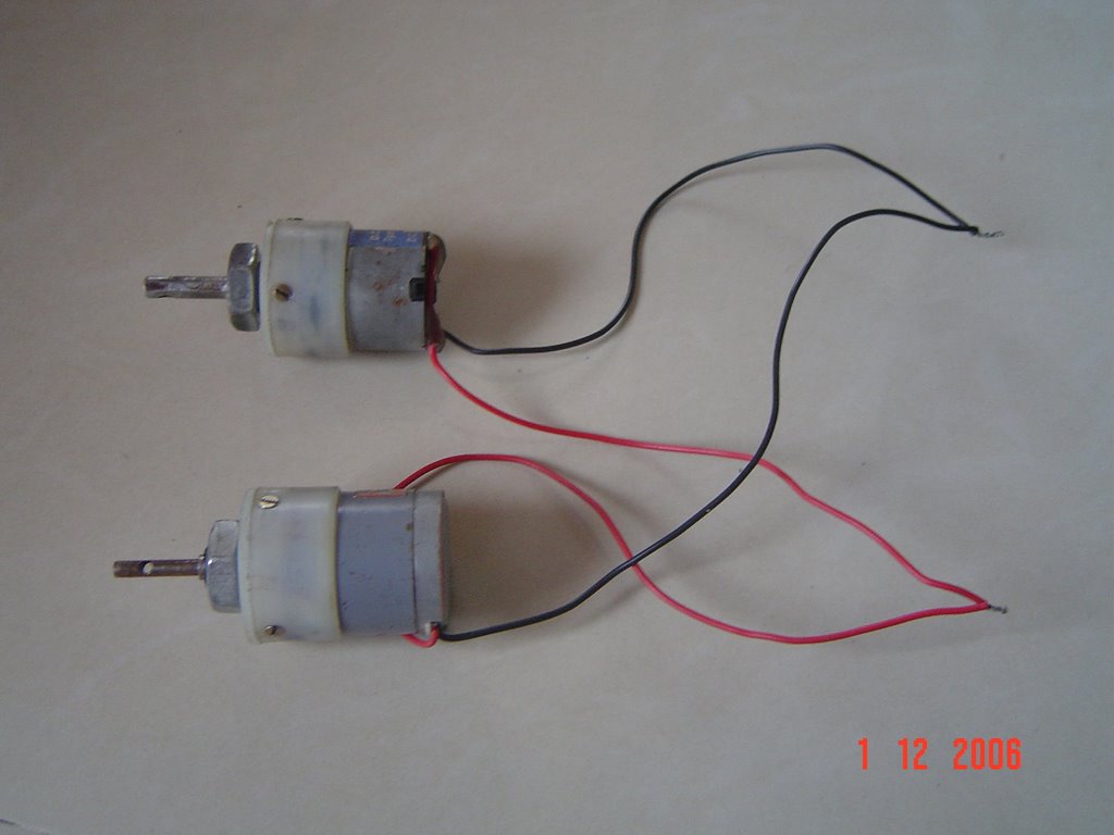
We will call the top and bottom motors on left hand side the left pair and
The top an bottom motors on right side the right pair
The above picture shows the left pair . similarly we have to connect the right pair.
LEFT PAIR MOTORS
We will bring together the positive of both the top and bottom motor on left hand side and sort them . similarly we will sort the negative of both the motors of the left pair.
RIGHT PAIR MOTORS
Now as we did in the left pair we will sort the +ve wire of both motors together and sort the –ve of the motors .
So in all we get 4 output wires from the motor connection .
2 from left pair and 2 from right pair.
COMBINING THE SWITCH AND MOTOR CIRCUIT
Now to connect the switch to motors we have to choose four output from the switch connection as we have four output from the motor connection.
We will consider the terminal 5 and 6 from the first switch and 5’ and 6’ from second switch.
Considering the terminal 5 from first switch positive terminal 5’ will be positive from second switch. Similarly 6 and 6’ are considered as negative.
Now the connection goes this way
positive wire combination from left pair motors will be connected to point 5
negative wire combination from left pair motors will be connected to point 6
positive wire combination from right pair will be connected to point 5’
negative wire combination from right pair will be connected to point 6’
these connections are made with the help of intermediate wires called the rainbow wires. I suppose…..
these are a bunch of thin wires used for internal circuitry.
If suppose u connect positive wire from left hand pair from motors to red wire then the other end of red wire will be connected to point 5.
Similarly for all connections.
The length of the intermediate wire depends on the user. Normally we take 8 to 9 meters. That will be the range of your robo.
Wednesday, December 12, 2007
Micro Robots

Swarm robotics is a new approach to the coordination of multirobot systems which consist of large numbers of relatively simple physical robots. The goal of this approach is to study the design of robots (both their physical body and their controlling behaviors) such that a desired collective behavior emerges from the inter-robot interactions and the interactions of the robots with the environment, inspired but not limited by the emergent behavior observed in social insects, called swarm intelligence. It has been discovered that a set of relatively primitive individual behaviors enhanced with communication will produce a large set of complex swarm behaviors.
Unlike distributed robotic systems in general, swarm robotics emphasizes a large number of robots, and promotes scalability, for instance, by using only local communication. Local communication is usually achieved by wireless transmission systems, using radio frequency or infrared communication.
Potential application for swarm robotics include tasks that demand for extreme miniaturization (nanorobotics, microbotics), on the one hand, as for instance distributed sensing tasks in micromachinery or the human body. On the other hand, swarm robotics is suited to tasks that demand for extremely cheap designs, for instance a mining task, or an agricultural foraging task. Artists are using swarm robotic techniques to realize new forms of interactive art installation.
Both miniaturization and cost are hard constraints that emphasize simplicity of the individual team member, and thus motivate a swarm-intelligent approach to achieve meaningful behavior on swarm-level.
Further research is needed to find methodologies that allow for designing, and reliably predicting, swarm behavior, given only features of the individual swarm members. Here, video tracking is an essential tool for systematically studying swarm-behavior, even though other tracking methods are available. Recently Bristol robotics laboratory has developed an ultrasonic position tracking system for swarm research purposes.
Swarm intelligence (SI):Swarm intelligence (SI) is artificial intelligence based on the collective behavior of decentralized, self-organized systems. The expression was introduced by Gerardo Beni and Jing Wang in 1989, in the context of cellular robotic systems.
SI systems are typically made up of a population of simple agents interacting locally with one another and with their environment. Although there is no centralized control structure dictating how individual agents should behave, local interactions between such agents lead to the emergence of global behavior. Natural examples of SI include ant colonies, bird flocking, animal herding, bacterial growth, and fish schooling.
In SI systems, the agents follow very simple rules generally out of the need for survial which leads to very complex rules/algorithms at the systems level.
The application of swarm principles to robots is called swarm robotics, while 'swarm intelligence' refers to the more general set of algorithms.
Example algorithms:
Ant colony optimization:
Ant colony optimization is a class of optimization algorithms modeled on the actions of an ant colony. Artificial 'ants' - simulation agents - locate optimal solutions by moving through a parameter space representing all possible solutions. Real ants lay down pheromones directing each other to resources while exploring their environment. The simulated 'ants' similarly record their positions and the quality of their solutions, so that in later simulation iterations more ants locate better solutions. One variation on this approach is the bees algorithm, which is more analogous to the foraging patterns of the honey bee.
Particle swarm optimization:
Particle swarm optimization or PSO is a global optimization algorithm for dealing with problems in which a best solution can be represented as a point or surface in an n-dimensional space. Hypotheses are plotted in this space and seeded with an initial velocity, as well as a communication channel between the particles. Particles then move through the solution space, and are evaluated according to some fitness criterion after each timestep. Over time, particles are accelerated towards those particles within their communication grouping which have better fitness values. The main advantage of such an approach over other global minimization strategies such as simulated annealing is that the large number of members that make up the particle swarm make the technique impressively resilient to the problem of local minima.
Stochastic diffusion search
Stochastic Diffusion Search or SDS is an agent based probabilistic global search and optimization technique best suited to problems where the objective function can be decomposed into multiple independent partial-functions. Each agent maintains a hypothesis which is iteratively tested by evaluating a randomly selected partial objective function parameterised by the agent's current hypothesis. In the standard version of SDS such partial function evaluations are binary resulting in each agent becoming active or inactive. Information on hypotheses is diffused across the population via inter-agent communication. Unlike the stigmergic communication used in ACO, in SDS agents communicate hypotheses via a one-to-one communication strategy analogous to the tandem running procedure observed in some species of ant. A positive feedback mechanism ensures that, over time, a population of agents stabilise around the global-best solution. SDS is both an efficient and robust search and optimisation algorithm, which has been extensively mathematically described.
Applications:
Swarm Intelligence-based techniques can be used in a number of applications. The U.S. military is investigating swarm techniques for controlling unmanned vehicles. ESA is thinking about an orbital swarm for self assembly and interferometry. NASA is investigating the use of swarm technology for planetary mapping. A 1992 paper by M. Anthony Lewis and George
A. Bekey discusses the possibility of using swarm intelligence to control nanobots within the body for the purpose of killing cancer tumors. Artists are using swarm technology as a means of creating complex interactive systems or simulating crowds. Tim Burton's Batman Returns was the first movie to make use of swarm technology for rendering, realistically depicting the movements of a group of penguins using the Boids system. The Lord of the Rings film trilogy made use of similar technology, known as Massive, during battle scenes. Swarm technology is particularly attractive because it is cheap, robust, and simple.
The inherent intelligence of swarms has inspired many social and political philosophers, in that the collective movements of an aggregate often derive from independent decision making on the part of a single individual. A common example is how the unaided decision of a person in a crowd to start clapping will often encourage others to follow suit, culminating in widespread applause. Such knowledge, an individualist advocate might argue, should encourage individual decision making (however mundane) as an effective tool in bringing about widespread social change.
Sunday, November 25, 2007
Information On Microcontrollers
Here's a list of Few of the many Microcontrollers which can b used in ROBOTICS..more updates will be there soon...
1)ATMEL AVR MICROCONTROLLER:
Features of ATmega128-16AI Microcontroller
• 128KB FLASH
• 4 KB RAM
• 4 KB EEPROM
• 53 I/O pins
• hardware multiplier
• Programming Lock for Software Security
• SPI Interface for In-System Programming
• Real Time Counter with Separate Oscillator
• 8-channel, 10-bit ADC:
- 8 Single-ended Channels
- 7 Differential Channels
- 2 Differential Channels with Programmable Gain at 1x, 10x, or 200x
• Dual Programmable Serial USARTs (2x UART)
• Master/Slave SPI Serial Interface
• 2x 8bit Timer, 2x 16bit Timer
• 16MHz RISC
ATmega128 TinyBoard Ver1.1
ATmega128 Development Board with ATmega128-16AI (16 MHz):
• super thin only 34mm x 40mm x 8mm
• full motherboard for ATmega128
• all pins are available on headers (2,54mm-/0,1" pitch), 2x15pins each
• high computing power
• easy to use: just connect to power supply (+5V) and program device
• separate grounds: analog and digital
• extra shielded
• ISP programming pins on right header
fully assembled board includes:
• ATmega128-16AI (-40 bis +85°C), X1 crystal 16 MHz, X2 crystal 32kHz (for
asynchron timer)
• header layout, schematics, programming tutorial
• female connectors 2 pieces (2x15 pins) also available
ATmega128 TinyBoard Ver1.2
ATmega128 Development Board with ATmega128-16AI (16 MHz) with ISP Header
same dimensions as Vers1.1 but with additional ISP header
• automatically switches off lines on right header when in programming mode (prohibits "shortages" during programming with the rest of circuitry)
• led indicates programming mode
• 100% pin compatible with Ver1.1
• super thin only 34mm x 40mm x 8mm
• full motherboard for ATmega128
• all pins are available on headers (2,54mm-/0,1" pitch) 2x15pins each
• high computing power
• easy to use: just connect to power supply (+5V) and program device
• separate grounds: analog and digital
• extra shielded
• fully assembled board includes:
• ATmega128-16AI (-40 bis +85°C), X1 crystal 16 MHz, X2 crystal 32kHz (for
asynchron timer)
• header layout, schematics, programming tutorial
• female connectors 2 pieces (2x15 pins) are also available
2)CYPRESS MICROCONTROLLER:
Features of CY7C68013A USB Microcontroller :
• Software: 8051 code runs from:
— Internal RAM, which is downloaded via USB
— Internal RAM, which is loaded from EEPROM
— External memory device (128 pin package)
• 16 KBytes of on-chip Code/Data RAM
• Four programmable BULK/INTERRUPT/ISOCHRONOUS endpoints
— Buffering options: double, triple, and quad
• Additional programmable (BULK/INTERRUPT) 64-byte endpoint
• 8- or 16-bit external data interface
• Integrated, industry-standard enhanced 8051
— 48-MHz, 24-MHz, or 12-MHz CPU operation
— Four clocks per instruction cycle
— Two USARTS
— Three counter/timers
— Expanded interrupt system
— Two data pointers
• 3.3V operation with 5V tolerant inputs
• GPIF (General Programmable Interface)
— Allows direct connection to most parallel interface
— Programmable waveform descriptors and configuration registers to define waveforms
— Supports multiple Ready (RDY) inputs and Control (CTL) outputs
• Vectored USB interrupts and GPIF/FIFO interrupts
• Separate data buffers for the Set-up and Data portions of a CONTROL transfer
• Integrated I2C controller, runs at 100 or 400 kHz
• Four integrated FIFOs
— Integrated glue logic and FIFOs lower system cost
— Automatic conversion to and from 16-bit buses
— Master or slave operation
— Uses external clock or asynchronous strobes
— Easy interface to ASIC and DSP ICs
Cypress CY7C68013A - 56 Development Board with USB2 HighSpeed MiniUSB:
• Cypress CY7C68013A-56PVXC - low power Version of CY7C68013-56, full USB2 specified
• tiny board, board dimesions 3,5cm x 5,1cm
• USB2 High Speed (480Mbit/s)
• Mini USB
• EEPROM onboard
• onboard voltage regulator (bottom side)
• GPIF Interface
• reset push button
• power led
• fully assembled board comes with MiniUSB-Cable and schematic
• female connectors 2x (2x12 pins) also available
FX2 / FX2LP Development Board
Cypress CY7C68013A - 128 Development Board with USB2 HighSpeed:
• Cypress CY7C68013A-128AXC - low power version of CY7C68013-128
• USB2 High Speed (480Mbit/s)
• EEPROM onboard
• 2 serial interfaces
• all pins out, ERNI-header
• IDE interface
• ERNI connector
• memory extention with maximum addressable memory
- 64 KB external SRAM with 15ns (memory included)
• 2x I²C PortIO Expander (2x 8 = 16 additional ports)
• reset push button
• board dimensions: full Euro PCB (160cm x 100cm)
• fully assembled board comes with USB-Cable and schematic
More Updates Soon Please Bear For Mean Time And If Any Specific Request Please A Comment.
Assembling A FLED Solar Engine Tutorials
1. Take the 3904 transistor and using a pair of long nose pliers carefully bend the collector leg (that's the one on the far right) so that it is perpendicular to the transistor body as shown in the photograph. Then again using long nose pliers carefully bend the emitter leg (the one on the far left) first perpendicular to the base leg (the middle one) but in the same plane and then back up towards the base leg as shown in the photograph. If you're not sure about this take a look at step 3 and 4 it might be clearer when you can see the assembled engine.
2. Take the 3906 transistor and bend the emitter leg (the one on the far right in the photograph) first perpendicular to the base leg but in the same plane and then over the top of the transistor body. Then take the base leg and bend it perpendicular to the transistor body as shown in the photo.
3. Hold one of the transistors with a pair of long nose pliers so that the base leg of the 3904 is next to the collector leg of the 3906. The legs should overlap by about 6mm - 8mm. With your other hand pick up your soldering iron (which should be hot !), clean the tip and then melt a little pool of solder on the tip. Apply the tip of your iron to the two legs of the transistors to be joined for a second (no more !). The legs will be heated and the solder should flow between them easily. Do not overheat (it may damage the transistors). Continue to hold the transistors together for about two seconds until the solder has solidified.
Now wipe the sweat from your brow!


4. Solder the 2.2k resistor between the collector leg of the 3904 and the base leg of the 3906 as shown in the photo. This is best done by first 'tacking' both ends of the resistor to the transistor legs with a small pool of solder on the iron and then applying additional solder to make a more secure joint, once the initial 'tack' has solidified. Using a pair of side cutters trim the excess lead from the resistor.
Almost there !

5. Carefully bend the negative leg (the shortest one and also the one nearest the 'flat' on the FLED body) of the FLED at right angles to the positive leg, as shown in the photo.

6. Slide a piece of heat shrink tubing over the FLED and using a lighted match shrink the tubing over the FLED body. Whilst the tubing is still hot pinch the end opposite the leads to seal the tube, then cut off any excess tubing.

7. Solder the negative lead of the FLED to the emitter of the 3904 (the one that is bent backwards) and the positive lead to the base of the 3906 (to which the resistor is also connected)

8. Trim off the excess leads : FLED negative, FLED positive and 3906 base - as shown in the photo
Microcontrollers
While people quickly recognised and exploited the computing power of the microprocessor, they also saw another use for them, and that was in control. Designers started putting microprocessors into all sorts of products that had nothing to do with computing, like the fridge or the car door that we have just seen. Here the need was not necessarily for high computational power, or huge quantities of memory, or very high speed. A special category of microprocessor emerged that was intended for control activities, not for crunching big numbers. After a while this type of microprocessor gained an identity of its own, and became called a microcontroller. The microcontroller took over the role of the embedded computer in embedded systems.
So what distinguishes a microcontroller from a microprocessor? Like a microprocessor, a microcontroller needs to be able to compute, although not necessarily with big numbers. But it has other needs as well. Primarily, it must have excellent input/output capability, for example so that it can interface directly with the ins and outs of the fridge or the car door. Because many embedded systems are both size and cost conscious, it must be small, self-contained and low cost. Nor will it sit in the nice controlled environment that a conventional computer might expect. No, the microcontroller may need to put up with the harsh conditions of the industrial or motor car environment, and be able to operate in extremes of temperature.
A generic view of a microcontroller is shown in Figure. Essentially, it contains a simple microprocessor core, along with all necessary data and program memory. To this it adds all the peripherals that allow it to do the interfacing it needs to do. These may include digital and analog input and output, or counting and timing elements. Other more sophisticated functions are also available, which you will encounter later
in the book. Like any electronic circuit the microcontroller needs to be powered, and needs a clock signal (which in some controllers is generated internally) to drive the internal logic circuits.
Microcontroller families
There are thousands of different microcontroller types in the world today, made by numerous different manufacturers. All reflect in one way or another the block diagram of Figure. A manufacturer builds a microcontroller family around a fixed microprocessor core. Different family members are created by using the same core, combining with it different combinations of peripherals and different memory sizes.
This is shown symbolically in Figure 1.9. This manufacturer has three microcontroller families, each with its own core. One core might be 8-bit with limited power, another 16-bit and another a sophisticated 32-bit machine. To each core is added different combinations of peripheral and memory size, to make a number of family members. Because the core is fixed for all members of one family, the instruction set is fixed and users have little difficulty in moving from one family member to another.
While Figure below suggests only a few members of each family, in practice this is not the case; there can be more than 100 microcontrollers in any one family, each one with slightly different capabilities and some targeted at very specific applications.
Microcontroller packaging and appearance
Integrated circuits are made in a number of different forms, usually using plastic or ceramic as the packaging material. Interconnection with the outside world is provided by the pins on the package. Where possible microcontrollers should be made as physically small as possible, so it is worth asking: what determines the size? Interestingly, it is not usually the size of the integrated circuit chip itself, in a conventional microcontroller, which determines the overall size. Instead, this is set by the number of interconnection pins provided on the IC and their spacing. It is worth, therefore, pausing to consider what these pins carry in a microcontroller.
The point has been made that a microcontroller is usually input/output intensive. It is reasonable then to assume that a good number of pins will be used for input/output. Power must also be supplied and an earth connection made. It is reasonable to assume for the sort of systems we will be looking at that the microcontroller has all the
memory it needs on-chip. Therefore, it will not require the huge number of pins that earlier microprocessors needed, simply for connecting external data and address buses. It will, however, be necessary to provide pin interconnection to transfer program information into the memory and possibly provide extra power for the programming process. There is then usually a need to connect a clock signal, a reset and possibly some interrupt inputs.
Figure above, which shows a selection of microprocessors and microcontrollers, demonstrates the stunning diversity of package and size that is available. On the far right, the massive (and far from recent) 64-pin Motorola 68000 dwarfs almost everything else. The package is a dual-in-line package (DIP), with its pins arranged in two rows along the longer sides of the IC, the pin spacing being 0.1 inches.
Because the 68000 depends on external memory, many of its pins are committed to data and address bus functions, which forces the large size. Second from right is the comparatively recent 40-pin PIC 16F877. While this looks similar to the 68000, it actually makes very different use of its pins. With its on-chip program and data memory it has no need for external data or address buses. Its high pin count is now put to good use, allowing a high number of digital input/output and other lines. In the middle is the 52-pin Motorola 68HC705. This is in a square ceramic package, windowed to allow the on-chip EPROM (Erasable Programmable Read-Only Memory) to be erased. The pin spacing here is 0.05 inches, so the overall IC size is considerably more compact than the 68000, even though the pin count is still high. To the left of this is a 28-pin PIC 16C72.
Again, this has EPROM program memory and thus is also in a ceramic DIP package. On the far left is the tiny 8-pin surface-mounted PIC 12F508 and to the right of this is an 18-pin PIC 16F84A.
Building A BEAM Symet

The symet for some reason always tends to be a three fold rotation symmetrical robot, but I like to push the envelop a little. The Quaret, hence its name, is a four fold rotation symmetrical robot. It's very small, very active, and a lot of fun to watch. So enough chit chat lets find some parts!
List of parts
(most are available at DigiKey)
-1 x cassette tape player motor (or equivalent)
-1 x Solar panel (i use the Panasonic sunceram 37x33mm)
-Coil of heavy gauge wire (copper is good, but anything will work!)
-1 x 2.2k resistor
-1 x CMOS 1381J (The letter denotes the voltage it is triggered at, try some higher or lower voltage ones if you want!)
-1 x 2N3904 NPN transistor
-1 x 2N3906 PNP transistor
-4 x 1000uF capacitors (these can be substituted for any rating wanted, just remember, the more capacitance the longer charge)
-small diameter heat shrink (for motor actuator)
-4 x small washers (you'll see)
-plenty of electrical tape!
Now go find those parts!!
Now that you have the parts
So you finally got all of the parts, good! It's a lot easier to build this bot when you have all those parts lying right in front of you, trust me!
Lets build our chassis

Gather together your tape player motor, your large value caps, and some heavy gauge wire. To build you chassis you'll need to glue you caps onto the sides of the motor, just remember we need to put those caps in a parallel circuit. You should either glue the caps with all the positive ends facing out, or with all the negative ends facing out (see illustration).
Once you have all of those caps on there, you need to solder the post together (see illustration). The outside post probably won't reach each other, so get that wire out. Make the wire into a small ring just big enough to fit around the posts, solder it into the ring. Then take and solder all those posts onto the ring (see illustration). The last step is to solder the inner post together, these should reach each other but if they don't, use the wire again.

(click for bigger pic)
On to the SE
Lets define what exactly a solar engine is
Solar Engine - a circuit used to drive a motor which requires several tens of milliamps, with a solar panel that produces only a few milliamps.
See the illustration for the freeformed layout of the 1381J SE. Pretty simple. If you've been involved with BEAM before, this circuit should seem quite familiar! Keep in mind when you make this circuit that you want to have plenty of lead to solder to, but not to much that its a burden.
Combining

(click for bigger pic)
You have the SE and the chassis lying next to each other, right? From here on out its a piece of cake. First thing to do is to solder you positive and negative leads to the rings on the caps, once you have that take you motor (some motor might have wire leads, some have solder tabs, use precaution either way, even the best screw up motors!) and hook it up according to the drawing of the SE, that middle lead goes to the negative and then you can hook up the other end to the positive (you can reverse that so the motor positive goes to the middle lead, but I just happened to draw it that way). Those leads should be stiff enough to hold up that solar cell, but if they aren't, you can use glue or anything to hold it down, just make sure it works first!
Finishing touches

(click for bigger pic)
It works, but doesn't move to well, eh? This is where the heat shrink and washers come in. first off, take some heat shrink and put it on that motor shaft, chances are that it will slip off right away. To rectify that put on another layer. From there you can add as many layers as you see fit, just remember, to get that nice rounded finish, cut the inner most ones shorter than the outer ones so they shrink inward to round off the edges. Now your Quaret works, but goes in little circles. It's time to talk about symet behavior.
Symets exhibit random behavior depending on their surroundings and the available light. The key to making a symet interesting to watch lies in the angle it leans at. If your symet leans at a 20 degree or more angle, chance are that its hard to tip and it just makes little circles. If you symet leans at a 18 degree or less angle it will travel almost in a straight line. If its too small an angle, it will tip ever trigger. So here's the down low on getting it to travel straight. The symet should trigger and the edge its leaning on should cause it to turn, but if you decrease the leaning angle, the motor shaft is more perpendicular to the ground causing it to torque the symet the opposite direction of the turn, making it travel straight!
The washer can be glued to the bottoms of the caps (see picture) to rectify angle. use hot glue here, this way, if want to move them to adjust angle, take a heat shrink gun (or equivalent, a.k.a. something hot) and melt the glue so you can move the washer.
One more finishing touch is to add electrical tape around the edges of the solar panel, it help to protect you solar panel from nicks and cuts. Just remember, A for aesthetics, keep it pretty!
How does it work?
By now your Quaret should be up and running, work well? I hope so, cause i was pleased with mine. Now its your turn to experiment, Symets are so simple you can easily come up with your own plans. Hope you no longer refer to them as the brainless 'bots, because a good symet can even display problem solving abilities, as well as brute strength.
KEEP ON BEAMing!!!
Introduction To BridgeWare
| |
| What is bridgeware? |
| Short answer: Bridgeware are components that bridge the gap between the worlds of computer programming and electronics. Longer answer: Bridgeware components translate the signals of external electronics hardware into a signal a computer can understand. They can be thought of as a form of adaptor board or signal converter board. Essentially bridgeware allows computer programmers to interface with electronics such as sensors and motor controllers right from their native programming environment. Most bridgeware comes with a software API which expose particular device functions to the developer. Some bridgeware has simple common serial interfacing and it's up to a developer to create their own API/Wrapper. Either way bridgeware allows programmers to do one important thing; reach out off their computer screens and allow their code to interact with the real world. |
| Who uses bridgeware? |
| Bridgeware components are used in robotics, home automation, data collection, RFID, and other similar areas. Bridgeware is most often used by educators, students, hobbyists, researchers, small businesses, and even artists. |
| What can I do with bridgeware? |
| The quick answer to that is, just about anything your imagination can think of. People build robots out of their PCs, automatic dog feeders, backyard water spraying defense systems, grill temperature monitoring systems, science experiments, school projects, quick pay RFID systems for restaurants, and all kinds of other fun projects. Any kind of bridgeware boils down to one of two main types of actions, sensory input or control output. Just exactly what you do with these two things is totally up to you! |
|
|
|
|
|
|
|
|
| Where can I see a list of all the types of bridgeware available? |
| Funny you should ask! It just so happens that we are the largest retailer of bridgeware. You can browse the catalog to see what kind of bridgeware components are out there. I/O Boards & Robot Controllers Motor Controllers Sensors Or visit the whole Parts Section to see everything To Know More About BridgeWare Check The Link In The Reference Section |


Introduction To PC Based Robotics

| What do we mean by PC based robotics? |
| We use the term PC based robotics in a very general sense. It refers to robotics that use any type of the wide ranging format of personal computers that we know today; desktop, laptop, mini, hand held, or a single board computer (SBC) for example. It can be running any kind of operating system and either be physically on the robot or used through distributed computing. Some defining factors are that the computer would have the familiar I/O and communications associated with modern computers; USB, serial, wireless communications, monitor, mouse, & keyboard ports. |
| Why is the PC ready now when it wasn't before? |
| There were three main reasons why roboticists were not adopting the use of computers as a processor platform of choice in the past: 1) Cost was too high 2) Size was too large 3) No robotics I/O available The first two problems, cost and size, have largely been solved. Single board computers (SBCs) are now getting down to the size of credit cards for a few hundred dollars. Size will continue to shrink as technology advances and form factors will also continue to emerge more suited for the needs of robotics. Low cost networking technologies are also now available for using computers which are not physically on a robot. The largest hurdle for roboticists in using a computer as their choice of processor platform was the lack of proper I/O needed for robotics. Common computers don't have analog and digital inputs or motor controller output ports. There are no A/D converters or places to input encoder signals like there are on more simple microcontrollers. In recent years a new realm of computer peripherals have emerged called bridgeware which solve the I/O issue for roboticists interested in using computers for their projects. Bridgeware components convert common computer I/O into robotics I/O, you can learn more about them here. |
|
|
| What do computers bring to Robotics? |
| A Standard Platform |
| As long as everyone is building robotics on vastly different processors we will never reach a point where there is transferability of technology in robotics. Moving to the 32 bit processor with the common I/O of computers allows roboticists to tap into the standards rich world of computers. This allows both software and hardware to become more transferable between users which allows for accelerated advancements. |
| High level Object Oriented languages, IDEs, and GUI |
| Software development on computers is a very mature and feature rich environment. The languages are powerful, the development environments are robust with extensive graphical tools, thousands of third party vendors build supporting tools for dozens of languages. Using a computer as the processor platform delivers all the powerful tools of computer programming and application development to the world of robotics development. |
| Tapping into the worlds largest pool of technical talent |
| The entry level bar for robotics currently is set pretty high. A person needs to be able to work with mechanics, electronics, and programming in order to build a robot. This poses a problem for the technology advancing since it reduces the amount of potential technicians that will be in the space. The electronics barrier is the most constricting of the three. For every electronic engineer in the world there are thousands of computer programmers. Computer programming is the most common technical skill in the world. Using computers and bridgeware in robotics development removes the electronics barrier to entry and allows robotics as a technology to tap into the massive talent pool of computer programmers all over the globe. This is something that will propel robotics forward. |

Thursday, November 22, 2007
Building a FRED Photopopper
Fred is my first 'photopopper' style bot. I had designed and built a similar bot before, but that one had three motors arranged radialy around a central axis. It didn't work nearly as well as Fred does.
The secret to Fred's success is the modified FLED solar engine circuit. I tried a FLED circuit, but the low-light performance was abysmal. I needed to put my 60W reading lamp 10 cm away from the solar panel before it would fire! This was clearly inadequate, so something had to be done. I tried putting in extra diodes, extra capacitors, extra resistors, and eventually settled on the design shown here.
Now Fred will pop away quite happily 40 cm from my desk lamp, which is the height that it normally sits when I'm reading. He will also pop all day when indoors, so long as a window is nearby to let in some diffuse daylight.
Specifications:
Voltages:
Switch-on: 2.4 Volts
Switch-off: 1.4, or 0.7 Volts, depending on what mood Fred is in.
Dimensions:
43 (length) x 27 (height) x 38 (width) mm.
Solar Cells:
One 33 x 24 mm Panasonic 5 Cell amorphous array (Part # BP-243318).
Storage Capacitors:
One NEC 0.033 Farad capacitor, with a 47uF cap in parallel to lower the internal resistance at switch-on.
Motors:
Two namiki pager motors, with extra padding on the shaft, directly resting on the ground.
Electronic components:
2 x BC337 NPN transistors
2 x BC327-25 PNP transistors
2 x Red Flashing LED (FLED)
2 x 3.3 K resistors
2 x 33 K resistors
2 x 4.7 uF capacitors
Performance:
Fred is quite an active bot compared to my other mobile bots. At 11:00 in the morning sun, he takes two seconds to recharge after a big step, and one second to recover from a small step. Sometimes he takes big steps, sometimes he takes small steps. When he takes a big step, the capacitor discharges all the way to around 0.8 Volts, but when taking a small step the cap discharges to only 1.5 or so volts.
This results in interesting behavior. It seems that he takes small steps when directly facing the sun, and big steps when facing at 90 degrees or more. If Fred starts out facing into the sun then he will take lots of quick, little steps of maybe 45 degrees and follow the sun around the sky.
But if you start with the bot facing away from the sun, or at 90 degrees, then he will take giant 180 degree strides, alternating sometimes with little steps to aim more towards the center of the light pool.
Construction and development:
I originally breadboarded a single FLED solar engine, and tested the circuit using this setup. This resulted in the poor performance that many FLED SE builders have experienced and cursed. I'm the sort of person who doesn't give up very easily (My friends just call me stubborn!) so I toyed with the circuit until it reached the stage it is now.
I started by experimenting with the 3.3k resistor. I found that the reason that many FLED SE's lock up in lower light levels is that the FLED is being kept high by this resistor. Current is going through the motor, through this resistor, feeding the FLED, but every time the FLED fires, it discharges a little bit from the storage cap. If the light level isn't sufficient to replace the charge lost each time the FLED fires, then you reach an equilibrium point where the SE appears to 'lock up'. I tried adding a diode in series with this resistor, but that didn't solve any problems - in fact it created some more! The SE would lock up at 0.6 volts instead of the more usual 2.2 V!
By this stage I was thinking about making the popper phototropic as well. I added a phototransistor to the anode of each FLED. This raised the switch-on level, but made the bot nicely follow the light.
I then thought about putting a capacitor in series with the FLED. My reasoning being that since the FLED only has to trigger the two transistors, not actually hold the base down, then you only need a little spike, not a long on-time. This proved to be the key to good performance. Of course, I also needed another resistor to discharge the 4.7 uF cap in between FLED flashes. I found that the best place to put this was on the motor terminal, instead of the base of the PNP transistor. The reason for this is that the motor terminal swings a lot more than the base of the PNP (2.2 V as opposed to 0.7 V), so it helped to 'latch' the circuit more easily.
My problem now was that the damn phototransistors were affecting the switch-on level too much. I wanted the bot to have a lower switch-on level in low light (because the solar panel won't produce as much voltage) but when I wired the PTs in that configuration, the switch on level would shoot up to 2.9 volts! This was way too high for me, so I decided that since no-one was looking, I would dispense with the PTs altogether and see how much the FLEDs were affected by changes in ambient light. To my delight, Fred saw the light and turned towards it! The changes in ambient light were enough to change the characteristics of the FLEDs, and make Fred choose the brighter side over the duller side when ready to fire a motor.
Tuning:
If you have a look at the schematic for Fred, you will notice that there is no way to 'tune' the circuit if one side of your photopopper is more likely to turn on than the other in equal light.
Bad luck.
The way I tuned Fred is that I selected two FLEDs that were as equal as I could find, in the selection that I had. The FLEDs are the most critical part of tuning. Get them right, and the rest just takes care of itself. So how do you choose two FLEDs that are about equal? Simple.
All you need is a solar panel (or a power supply with a 2.2k resistor in series), and a reasonably large storage capacitor. Put the solar panel, the cap, and two FLEDs in parallel, + to +, - to -. Short out the cap, and wait for it to charge up. The FLEDs should come on at around the same time, and should flash with equal brightness as the storage cap charges up. Go through your selection of FLEDs to find two that are as similar as you can find.
A better way to do it is with a multimeter. Put the meter on resistance measurement, put the FLED in a dark environment, and measure the resistance. Do this for all your FLEDs. I was amazed at how much variation there is in a batch of the same FLEDs: I had measurements from 0.5 MegaOhms to 8 MegaOhms. FLEDs within 95% of each other should work fine. Putting a 0.5M and a 8M FLED into the one popper will give a very lopsided outlook on life.
Measure the resistance twice to see how much your test setup has changed between measurements. This will give you an idea of how sensitive these components are.
Of course be careful not to let your fingers touch both leads at once! This will distort your measurement a lot.
Here you can see all the parts that you need to get going:

Here's a parts list to get you started: (from left to right, back row first)
1 x 3300 uF capacitor - DigiKey
2 x fuse clips - Hardware store
2 x 0.22 uF tantalum capacitors - DigiKey
2 x BC327-25 PNP transistors (2N3906 can be substituted) - DigiKey
2 x BC337 NPN transistors (2N3904 can be used instead) - DigiKey
2 x pager or similar motors- Solarbotics, MPJA, Big Micro
2 x 33k resistor (orange orange orange, or orange orange black red) - DigiKey
2 x 3.3k resistor (orange orange red, or orange orange black brown) - DigiKey
2 x red FLED (Flashing LED) - DigiKey
1 piece of 3mm heatshrink - DigiKey
1 paper clip
1 solar panel (at least 2.4 volts) - Solarbotics, Adaptobotics
The storage capacitor here is 3300 uF. You can try any value up to 0.047 F, but 2200 - 3300 uF will work the best.
? And here's a schematic to refer to later on: 

If you don't have a solar panel, then you can replace it with a battery (more than 3 volts) and a 2.2 k resistor in series with the battery. Hooking a battery up directly will probably damage your transistors, so remember to use at least a 470 Ohm resistor when using batteries.
To find two matched FLEDs, you will need a multimeter. Put the meter on resistance measurement, put the FLED in a dark environment, and measure the resistance. Do this for all your FLEDs. I was amazed at how much variation there is in a batch of the same FLEDs: I had measurements from 0.5 MegaOhms to 8 MegaOhms. FLEDs within 95% of each other should work fine. Putting a 0.5M and a 8M FLED into the one popper will give a very lopsided outlook on life.
Measure the resistance twice to see how much your test setup has changed between measurements. This will give you an idea of how sensitive these components are.
Of course be careful not to let your fingers touch both leads at once! This will distort your measurement a lot. If you absolutely can't find two FLEDs that are similar, then you will need to use the schematic at the bottom of this page to balance your FRED and stop him going in circles.
Testing:
Put some light on the solar panel, and watch the motors. If one of them fires then well done! The most common mistake here is to not let the motor leads make good contact with the holes. This will result in a cap voltage that will sit at about 0.7 volts. Put some extra solder on the motor leads or solder them to some normal hookup wire to sove this problem.
You should be able to make a particular motor fire by covering that FLED with your finger. This will put that side into darkness, so that side should fire. If you can make both sides fire like this then congratulations! Go on the construction.
If only one side fires, then take the FLED out for that side. Then debug the side that isn't firing. If your other side now fires then your FLEDs are mismatched and you either need to find some better matched FLEDs or use the schematic at the bottom of this tutorial.
Construction:
Lets start with some mechanics. While your soldering iron is heating up, grab a pair of pliers and the paperclip.
You need to cut both the inside and the outside loops of the paperclip at the point where the inner loop bends. This will give you aroundd rectangle, the size of which is dictated by the size of your paperclip.

By the time you've gotten that puzzled out your soldering iron should be well and truly hot. Tin (put solder on) the top of both fuse clips and the outer bends of the paper clip. Make sure that you heat all metal pieces up till they are very hot - and don't have the motors in the fuse clips when you do this! Attach the fuse clips to a fuse or something that doesn't mind heat. The solder should flow on easily, and shouldn't be able to be picked off later with a file.

Don't leave the motors in the fuse clips for the next step. Use a couple of old fuses or pencils or something, but don't use motors. You now need to put the paper clip on top of the solder blobs, and attach both fuse clips to the paperclip. This is harder than it sounds. Remember to orient the fuse clips at 45 degrees to the paperclip (so they are at 90 degrees to each other) and get the little tab on the fuse clip around the right way so that your motors will actually fit in the way they are intended (pointing away from each other, not towards each other).
This is what it should look like when you're done:

(Note the amount of solder I used. This isn't due to mechanical ineptitude... at least that's my excuse and I'm sticking to it!)
Now wait until it's all cooled down and stick your motors in. Check that the angles are vaguely symmetrical. If not, start again :-)
Now attach the negative lead of the capacitor to the center of the top rail of the paperclip. The paperclip should be on the opposite side of the motors to the capacitor. Bend the capacitor lead around the paperclip, and belt it with some heat and solder. Make sure that the positive lead doesn't touch the bottom rail of the paperclip. You are going to stick the solar panel on top of the cap and motors, so make sure that they create a flat surface to anchor the solar panel to.

Now it's time to start on the hard part: the electronics.
Firstly note the differences between BCxx type and 2N39xx type. This tutorial is aimed at using BC style transistors. If you're using 2N39xx transistors then the pinouts are different, so you'll have to be very aware of how your transistors should go in.
Put the BC327's into the body of the FRED, next to the capacitor, and connect up the emitters:


Now put the BC337's into the FRED, connecting up their emitters as well:


If you are using 2N39xx transistors, then these diagrams are incorrect. Flip these diagrams horizontally, and they will be right.
*** Important ***
Check, check and recheck all the transistor connections. Go back to the transistor pinout diagram and the schematic, and make sure that all the right pins are connected to the right places. It's easier to do it now than later, trust me.
If you don't do it now, you will be doing it later.
Now connect the base of the BC337 to the collector of the BC327: Note: Thanks to the eagle-eyed Joel Hirtle for picking up the mistake that was in the last sentence!

You will now need to put the 3.3k resistors in, connected between the collector of the BC337, and the base of the BC327:

Here's what it will actually look like from above:


Now lay the 33k resistors to the side of the 3.3k resistors and connect one end of the 33k to the back end of the 3.3k:

Now connect your 0.22 µF capacitor between the forward ends of both the resistors:


You now need to attach your FLEDs to the robot. Bend the FLEDs in the angle shown here: (the negative side of the FLED is at the top of this picture)

The negative lead of the FLED should now be attached to the blob of solder on the top of the robot that conects the negative lead of the capacitor to the paperclip.

The positive lead of the FLED is attached to the 33k resistor and 0.22 µF capacitor:

All that remains now is to attach the motor leads and the solar panel. To check the motor lead polarity, grab a 1.5 V battery, and connect it up to a motor. Figure out which way around gives you a forward kick. Do this for the other side as well. (one batch of pager motors went different ways - the only way to know is to do this check). Now, attach the lead of the motor that you had attached to the positive terminal of the AA to the positive lead on the capacitor. Attach the other lead of the motor to the back end of the 3.3k resistor on the side that the motor lives on.

This shot isn't that clear, but you should be able to see the orange leads from the motors here. The black leads seem to be lost in the ether... Now for the final connections: the solar panel. Connect the positive lead of the solar panel to the positive lead on the capacitor, and the negative lead to the paperclip:

Now for the acid test: Hold your creation up to a light globe or the sun. If the motors fire, then well done! If not, then check all your connections again. This circuit is a bit chaotic in nature - if the 'dark' motor doesn't fire the first time around then it might fire the second time around. Don't give up hope the first time the 'wrong' motor fires. Remember: your circuit worked on the breadboard, so it should work when freeformed. You did breadboard it, didn't you?

If you are having trouble getting your FRED engine to fire well, put a 1 uF cap across the motor terminals. This is a bit counterintuitive but for some reason this makes the motors turn on harder. Thanks to Kyle Simmons for this tip!

For the more adventurous, here's the schemtic of the complete FRED popper, complete with touch sensors, and a balance pot to make sure that your little FRED goes in a straight line. The bits in red are there to balance out any differences in the FLEDs, and the blue parts are there so that you can add tactile sensors to your creation. Good luck!


